The six speed constant mesh gear box has two shafts, one for the input and the other for output. Six gears are mounted on both the shafts and are in constant mesh. Ball bearings are connected to the gears on the output shaft which makes them to rotate freely on the output shaft. Most of today's single countershaft transmissions are constant-mesh and. Non-synchronized regulated spring-loaded synchronized. Which of the following refers to the fact that the auxiliary section gearing is not permanently connected to. Constant Mesh Gearbox: In constant mesh gear box all the gears are always in mesh and the engagement between the gears which are freely rotating on the transmission main shaft and the transmission main shaft is effected by moving the dog clut. Figure 13-7.-Constant-mesh transmission assembly—sectional view. All transmissions do not have four speeds forward, and all do not have the same gear reductions at the various speeds. Passenger cars, for example, usually have only three forward speeds and one reverse speed. Their gear ratios are about 3 to 1 in both low and reverse gear combinations. Synchro refers to the mechanism that allows changing gear ratios in a manual transmission as seen above. The gears on the mainshaft are on needle bearings and are locked to the shaft by the sleeve which is splined with the hub that is splined to t. Best mac programs.
 Constant mesh gearbox is a type of Transmission in which all or most of the gears are always in mesh with one another, as opposed to a sliding-gear transmission, in which engagement is obtained by sliding some of the gears along a shaft into mesh. In a constant-mesh manual gearbox, Gear ratios are selected by small Clutches that connect the various gear sets to their shafts so that power is transmitted through them. The following diagram shows the arrangement of a constant mesh gear box
Construction and working of a constant mesh gear box
Constant Mesh Transmission Explained
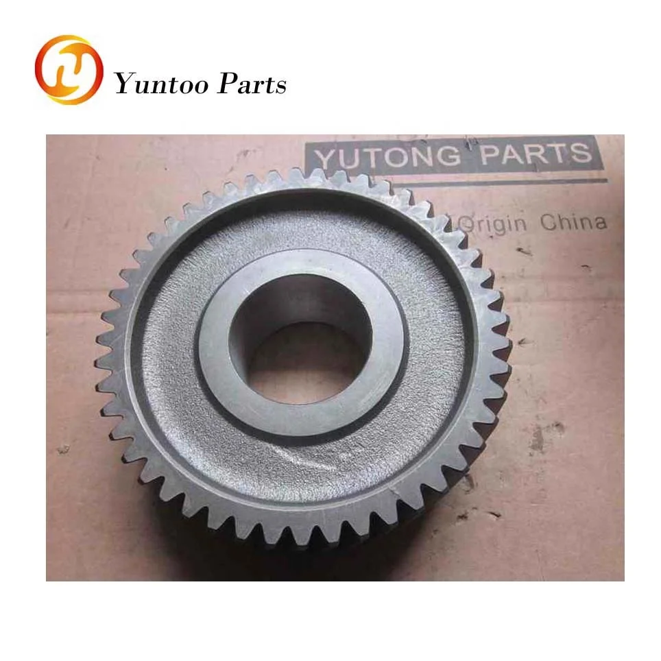
Constant gear mesh gearbox employed helical gears for power transmission. The gears are rigidly fixed in the lay shaft. The gears in output shaft rotates freely without engaging with shaft, thus not transmitting power. The gears in both shafts are always meshed together.

Constant Mesh With Mechanical Shuttle

When the gear lever is pushed,the gear selector fork pushes the dog clutch. The dog clutch engages the gearand the output shaft, thus power from lay shaft now transmitted to outputshaft. Free adobe acrobat reader.
Constant Mesh Transmission Definition

Constant Mesh Transmission Motorcycle

